|
|
|||||||||||||||||||||||||||||||||||||
|
Power Requirement & Battery Tests |
|
||||||||
| Unit | Notes: | ||||||||
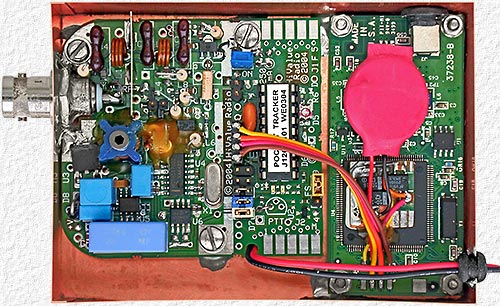
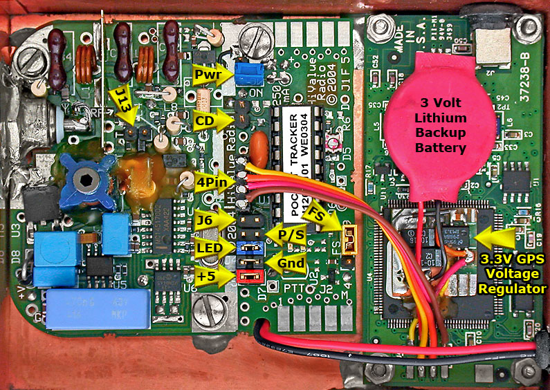
| Pocket Tracker |
Reverse Polarity Protection Diode Voltage Drop = 0.8 volts. |
||||||||
| RF Output Power - Supply Voltage - Minimum Voltage - Idle Current (No LEDs) - Transmit Current - |
250 mW 9 VDC - 6.1 VDC 4 to 5 ma 138 ma |
||||||||
| Lassen LP GPS Receiver |
GPS is powered from a 3.3V linear regulator powered |
||||||||
| Supply Voltage - Receiver Current - Active Antenna Current - |
3.3 VDC 54 ma 10 ma |
||||||||
| 6.1 to 9 VDC Total Continuous Current = 69 ma Peak Current = 202 ma |
A 9V Duracell Alkaline Battery provided 5.5 hours of operation during a battery test with the tracker beaconing once / minute. |
||||||||
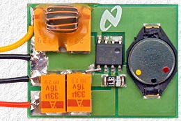
| Using 6 AA cells to increase the operating time adds significant weight so some experimenting was done with switching regulators, converters and different battery sources to try to increase efficiency, operating time and reduce weight. |
|
The 3.3V GPS receiver requires 64ma which is over 91% of the total tracker power requirement with the Pocket Tracker requiring a continuous average current of only **6.1 ma. so the largest improvement would be to replace the GPS 3.3V linear voltage regulator with a switching regulator. (**5ma continuous + 1.1ma average current resulting from 138ma for ≈1/2 sec every 60 sec's while transmitting APRS data). |
||||||||||||||||||||||||||||||||||||||||||||||
|
Table 2 lists the required current vs. supply voltage using the switching regulator to power the GPS Receiver and percent difference from using a linear regulator. |
||||||||||||||||||||||||||||||||||||||||||||||
|
||||||||||||||||||||||||||||||||||||||||||||||
|
This is how the tracker was powered for SABLE-1, with a switching regulator for the GPS and from a 9V alkaline battery. There was no time to perform a proper battery life test before the flight, but the tracker was used while travelling to Hanna to launch SABLE-1 and it is unclear as to when the tracker actually quit operating, but it appears the 9V alkaline battery lasted about 6 hours. With less current required at voltages greater then 6.1 volts (minimum pocket tracker operating voltage) it was hoped a 9 volt battery would last a little longer then it appears to have, but having the battery on the very hot dash board of my car that day likely didn't help. |
||||||||||||||||||||||||||||||||||||||||||||||
 |
Some work was also done with this converter which converts 2 to 4.5 VDC from 3 AA cells, which weigh the same as a 9V alkaline battery, to 6.3 VDC. Inexpensive no-name alkaline AA cells were used for a test and provided 7.8 hours of operation which is a 48% increase in operating time over using a 9V battery. No further work was done with this regulator, but the next step would have been to change it to provide 5V and simply remove the Pocket Trackers linear regulator for a further improvement. |
| To BEAR Home Page |