|
BEAR-1 APRS Tracker |
|
|
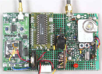 |
APRS Tracker Top View. Tracker modules were installed and interconnected on a |
|
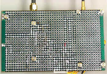 |
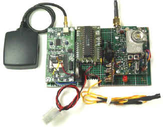
APRS Tracker Bottom View This shows my method of making one-of-a-kind printed circuit boards. Parts are installed as physically required and to minimize jumpers. Connections are then made by bridging pads together with solder. |
|
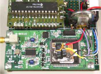 |
The Programming Cable connector is the white connector in the upper-right corner of the image. The GPS lithium backup battery is upper-right, standing up next to the MIM module. The GPS receiver is at the bottom of the image with the |
|
 |
Closer View of the
|
|
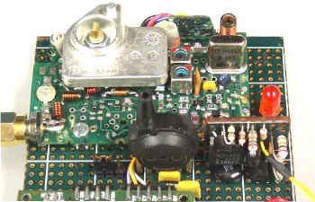 |
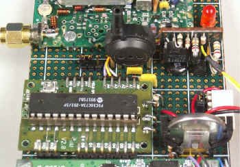
Closer View of the transmitter area. Circuit board to the right of the pressure transducer is Left of the pressure transducer is a jumper to The Orange LED indicates when the transmitter is keyed. |
|
|
The minimum supply voltage for providing position reports is 4.05 VDC, however a minimum of 5.15 VDC is required for proper operation of the MIM analog input circuits. The maximum supply voltage is 12 volts, but transmitter power varies with supply voltage and 6 volts provides almost 2.5 W of RF which is more than adequate for tracking balloons. More cells provide more voltage and output power, but simply adds excess weight and also shortens how long the battery will last. |
||
| To BEAR Home Page |