|
VHF End-Fed Half-Wave J-Pole
Antenna for High Altitude Balloon Use
May - 2006

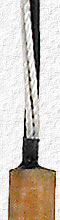
This is the impedance matching transmission line portion of the 2nd APRS antenna built and used for SABLE-1 & SABLE-2.
The feed line enters at the left end and the first few inches of the half-wave radiating element can be seen
at the right.
I needed an antenna for SABLE-1 and was tempted to use a small helical rubber duck antenna that could be installed on the tracker and simply placed into the payload box with it. But a rubber duck is a terrible antenna that's only designed for short-range hand-held use. It's also a
1/4 wave antenna that requires a ground plain or some type of counterpoise to operate properly and I wanted something better that didn't require a ground plain, like the half-wave center-fed folded dipole antennas we've been using. I doubt there's anything easier to build that would perform
as well as the folded dipole antennas, but a half-wave end-fed antenna that can be simply hung from the payload box would be much easier to use so I once again began searching the web for antenna information and proceeded to try and build one.
August - 2007
This page WAS  and I HAD planned to finish writing about the two end-fed antennas that were built and used, but what you see is all there will ever be as I forgot to take many photos of their construction, have lost all the scrapes of paper
with measurements and other info, and have too many other projects & too little time. and I HAD planned to finish writing about the two end-fed antennas that were built and used, but what you see is all there will ever be as I forgot to take many photos of their construction, have lost all the scrapes of paper
with measurements and other info, and have too many other projects & too little time.
These are J-Pole type antennas with 300 ohm TV twin-lead feed-line for the matching section and piano wire for the 1/2 wave dipole. They work excellent, are fairly easy to build & fairly light weight, but nearby objects affect them much more then the Folded Dipole
Antennas, tuning requires a lot of trial & error and time (see below) and they are heavier then I would have liked for balloon use.
I tried a number of different coils, tapped coils and transformer designs for matching 50 ohm feed line to the high impedance at the end of a half-wave dipole, but they were all extremely sensitive to anything nearby and very hard to adjust for a decent match.
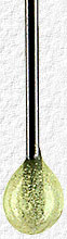
The matching section was built similar to the Folded Dipole Antenna, with balsa wood strips and epoxy resin for strength and protection, and the dipole was made from 1/16" dia. piano wire. Hobby store piano wire is normally only 36" long, but the dipole is a bit longer so a 36" length was extended
with a short piece near the top of the matching section using a small length of brass tubing over the joint and silver solder for strength. SABLE-1 proved this joint wasn't strong enough so a 2nd piece of brass tubing, of the next larger size, was used over the first. More important
was that the missing piece of 1/16" dia. wire was replaced with 1/32" dia. wire which I didn't have to use when building these antennas.
| A perfect 1:1 match was able to be achieved at 144.390 MHz |
|
VSWR was
and
VSWR was
|
< 1.2 from 143.0 to 145.8 MHz
< 1.5 from 142.3 to 147.0 MHz
= 2.2 with the antenna laying flat on the earth.
|
Antenna #1 Weight:
Antenna #2 Weight: |
82 grams (2.9 oz)
80 grams (2.8 oz) |
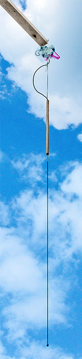
Length = 55" |

A few photos were taken while testing the finished antennas and the one pictured above was the 1st one built and prototype for the one seen at the top of the page. The matching section was sealed & protected using heat shrink tubing and doesn't look that great,
but the antenna works very well and was used for SABLE-3 whose 300mW APRS signal was heard over 600 km away.
|