 |
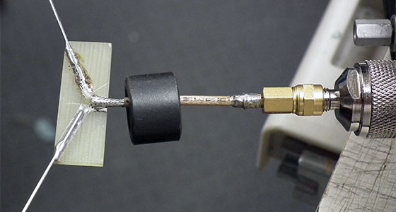
After the BEAR-6 problem I decided to make the PCB larger so the coax could be fastened in a way that prevented further coax problems. I also decided to test using a ferrite toroid core as a balun.
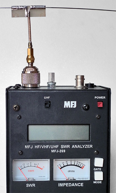
A ferrite toroid core on a coax feed line near the feed point of a balanced antenna acts as a RF choke and prevents the coax shield from coupling with the grounded dipole element and becoming part of the antenna and radiating power. Without such a balun,
antenna impedance measurements become sensitive to the configuration of the feed cable and the antenna radiation pattern will be distorted by radiation from the cable, but with our tracker antenna feed line lengths being so short (< ¼-λ length in most cases) I didn't expect to
see a toroid core make much difference, however I was wrong and it made using the antenna analyzer much easier by reducing the SWR and Impedance changes seen each time the analyzer was handled and/or moved. However I doubt any noticeable difference in the received signal would
ever be seen when tracking a payload, especially with how much the antenna pattern is already affected by the constant antenna movement during a flight, but decided to use a toroid core anyway as this would also prevent coax movement and further coax problems.
|
 |
|
My Latest HAB Tracker Antenna Design
|
|
|
I needed to make a number of antennas so I began by using a CAD program to create a cutting pattern that was copied and pasted as many times as could be printed on a sheet of paper. Each sheet was then cut up into individual patterns that were each glued
to a PC board using Elmer's rubber cement to make later removal easy.
The PC boards were cut to the required size from larger sheets of single sided 1/16" (.062") copper clad fibreglass PC board material.
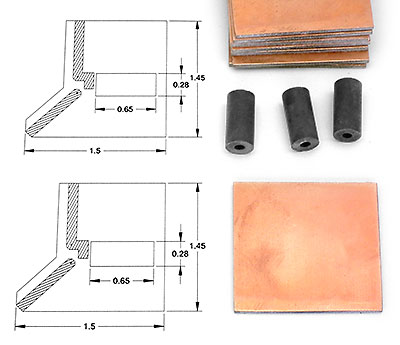
The ferrite toroid cores are nothing special and simply what I had salvaged in the past and had a hole dia. the same, or only very slightly larger, than the outer dia. of the RG-316 coax used. (I never toss anything without first saving everything from
the item that I may possibly need someday and these cores with a small inner hole dia. are the type sometimes found used for RFI suppression on small dia. audio lines and other such wiring.)
2 music wire antenna elements, each about 21" long, will also be required along with some RG-316 coax and an appropriate connector.
|
   |
|
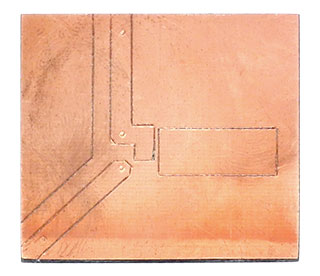
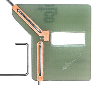
Left - an exacto knife was used to cut through the patterns and transfer the layout pattern to the boards.
Center - the paper pattern is then removed and the cuts inspected to ensure they cut though the copper layer completely.
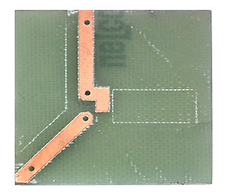
Right - The unwanted copper is removed by heating it with a soldering iron to soften the glue and then simply pulling the copper off. If there's a problem with getting a good transfer of heat from the soldering iron to the copper,
simply use some solder and the heat will transfer nicely and make the copper easy to remove as the solder is flowed across the surface.
|
   |
|
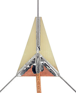
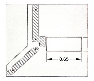
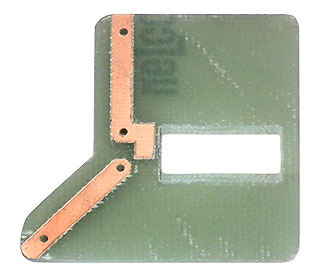
Left - Holes for the elements are drilled, the board is cut to shape and the opening the ferrite core fits into is cut out. Note that 2 sides of the opening are bevelled for a better fit and to help keep the core positioned while it's glued in place.
Center - One end of each element is bent into the shaped shown, the elements are installed through the holes and then the longer section of each one is bent down to lie flat against the backside of the board. Once soldered, the excess
length of the shorter bent section of each element is cut off flush with the board using a dremel tool (as seen in the right hand image below of the board back side).
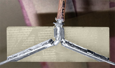
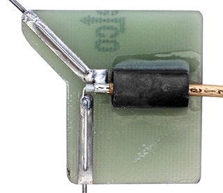
Right - The elements are soldered in place, the coax is fed through the toroid and then the core is glued in place with epoxy. It's important to have the feed line, or other small length of coax, fed through the toroid while it's glued
to ensure it's positioned exactly right as a fraction too low and you wont be able to fit the coax through later or a fraction too high and the coax won't lie flat against the PCB.
|
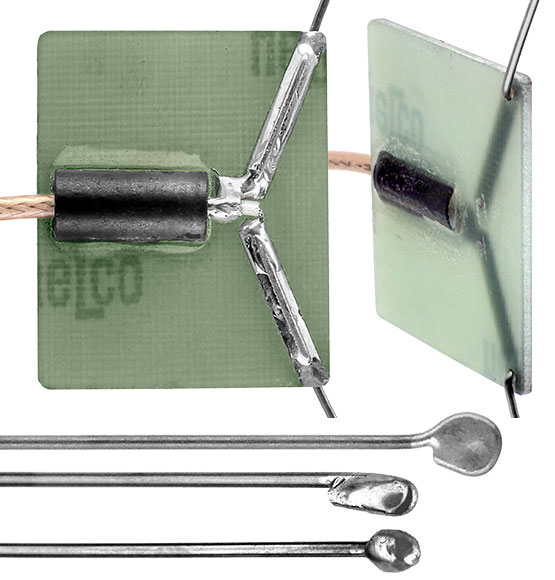 |
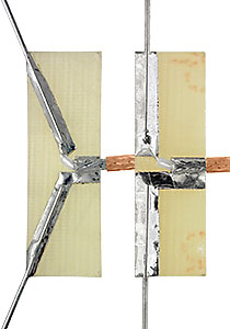
The right hand image shows the back side of the board and how the ferrite core is installed partially through the board so the coax may lay flat against the board where it's soldered. This image also shows how the excess length of each
element that protruded through the board has been cut off flush with the board.
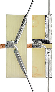
You may have noticed that the photos show 3 different antenna styles. Above left is one with the active element sloped down, above center with it straight down and left is a combination of the two and the one I've built antennas for,
and myself, have used the most.
The last 2 steps are to cut the elements to the right length so as to end up with each element 19-5/8" long from the center point between the two elements to each tip after providing some form of eye protection at the tips which otherwise
could easily poke an eye out. These 2 steps take some planning of course to not end up with the elements a bit too short or too long. Forming a tiny loop and filling it with solder to ensure nothing can get snagged through it is the hardest, but provides the best
protection and actually pretty easy once you get the hang of it. (Filling the loop with solder may be overkill, but I don't like to leave anything to chance - plus it looks nice.) Something much easier is to simply bend the end of each element back over itself and
flow solder over the fold to smooth things out and give the end a more finished look. A nice big round ball of solder at the tips could also be used, but forming a ball rather than simply tinning the end of an element is much harder than it looks and takes some
skill and practice.
|
|
 |
For additional element length details see this detail.pdf and feel free to download and use, modify or whatever my PCB Layout Sheet.pdf.
A few additional notes:
I started out using .031" dia. music wire to save weight, but SABLE-4 identified a problem with that and now use .039" dia. (17 gauge) music wire.
Music (some call it piano) wire is easiest to find in most any hobby store dealing with R/C aircraft. It's sold in 36" lengths and ≈ 21" is needed for each element so there's a fair bit of waste if building a number of antennas and you may want to find
a different source like I did. Piano tuners buy piano wire in large spools and I found one close by that was willing to sell me several hundred feet.
Always use RG-316, or a similar type teflon coax, that isn't affected by heat and melt when soldered.
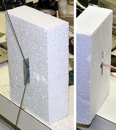
I've been making our payload boxes from 1-1/2" styrofoam and installing the antennas by simply cutting a slot in the foam, making a hole midway along the slot large enough for the SMA antenna connector to pass through and after the SMA connector and
feed line has been fed through the hole into the box simply pressing the antenna PC board into the slot until the pear edge of the board is flush with the inside of the box.
|
|
Knowing antenna theory and that an antennas impedance and SWR is optimum is all well and good, but in the end, the only thing that really matters is how well the antenna performs in actual use and after a number of flights I've seen
no noticeable difference between using these center-fed antennas with either in-line elements, elements at 90° or elements at 135° to each other.
Most don't consider short rubber duck type antennas < ¼-λ length to be a real antenna, at least not one suitable for HAB use and a problem with any full size antenna is that they are too large to fit inside
most payload boxes and the elements almost always end up becoming tangled in the lift line during post burst chaos and descent. I've considered setting up a UHF i-gate station for our balloon flights so smaller antennas that would fit in payload box could be used, but after seeing
no difference between using my antennas with in-line, 90° and 135° elements I decided to try something else first on our BEAR-13 flight.
|
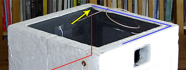 |
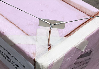
The payload box was a 13" cube made from 1.5" thick foam and I decided to try simply bending the elements as needed to fit the box. The yellow arrow points to where the antenna PCB was located. The blue line shows the
path of the grounded element along the top inside corner of a side wall and then, after a 90° bend, pressed into a slot cut down the center of the front wall top edge. And the red line shows the path of the active element down the back inside corner, through the
foam bottom and then, after a 90° bend, pressed into a slot cut in the bottom foam next to the rear wall.
|
|
|
A back-up tracker with an in-line antenna was used in addition to the payload tracker with the bent-to-fit-the-payload-box antenna during the flight and I was surprised to see no difference between the two in
the number of position reports logged by aprs.fi or we received directly while tracking the payload. As a result, I'm planning to make future payload boxes no smaller than a 11" cube and install a bent-to-fit antenna in each as the boxes are made.
|
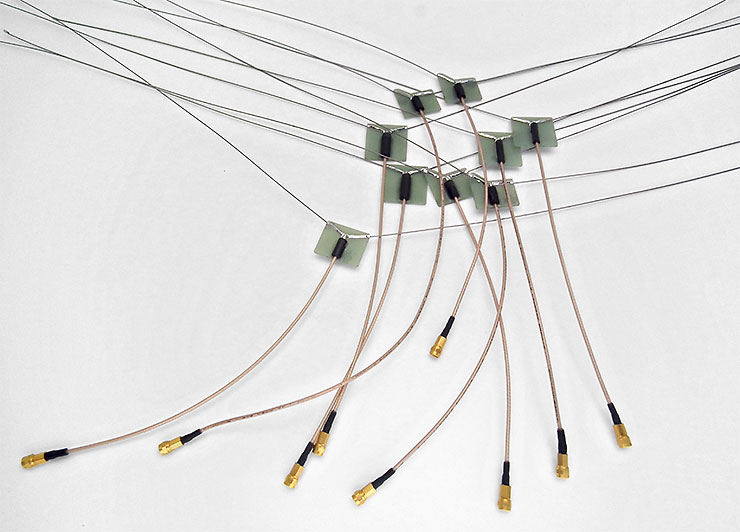 |
Some of the antennas made before running out of salvaged ferrite cores.
There may be a better core material to use than whatever my salvaged cores are made of and with no more cores to use I've been searching for what's best to purchase.
Selection is very limited with needing needing a specific inner dia. hole size, but I managed to find one the same size as one of my salvaged cores that's specified for VHF use and is an Amidon FB-31-0202.
|
|
|
Be sure to also see Part 2 - A VHF 1/2-Wave Center-Fed Dipole Antenna for a HAB Back-Up Tracker
|